Understanding the UBI File System in Embedded Devices
Published at – 11 min read – 2300 words
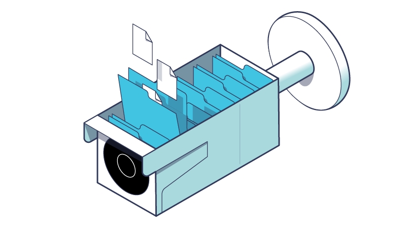
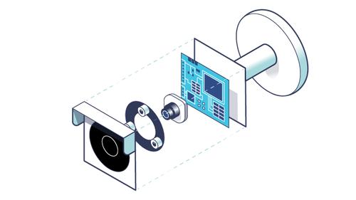
In Part 3 of our series, we explored the hardware device elements of the Reolink RLC-810A ― focusing on the NAND memory. We continue with Part 4 of our exploration into an IP camera firmware through introducing the concept of a file system. Furthermore, we will explore the technical reasons for choosing the UBI File System (UBIFS), a file system used especially for a category of mass storage, and we will unpack the UBIFS part using the ubi-extract tool.
An Introduction to File Systems
Once the booting phase has been introduced, we need to understand which components detected by Binwalk can be useful for our investigation and which cannot. From Part 1, we have seen that Binwalk shows a number of results. In particular, we are interested in the kernel image and the file system image.
Empirically, we can see that within the image that Reolink provides to its customers, there is a part dedicated to the UBI file system. It is imperative to understand the peculiarities of this file system in order to get to the bottom of the design choices.
Let’s begin by explaining what a file system is. All information processed by an electronic device can be divided into two categories: volatile information (when the device is switched off, it is lost) and non-volatile information. Depending on the mass storage used, non-volatile information (which remains even in the absence of electrical power) can be stored sequentially or randomly. Put another way, content can be written and read in multiple ways: sequentially (the file is memorized bit by bit) or randomly (pieces of file are placed in random places). Additionally, the operation of reading and writing can be executed by laser or by magnetic heads. In short, there are many different technologies to make a piece of data fixed.
At a high-level, however, we find a set of abstractions common among all memory types: the concept of files, write operations, read operations, creation of new files, and many other operations. Between this set of abstractions and the low-level controllers that only deal with input/output operations, there is a particular architectural layer called the file system that organizes information logically, structuring it into files and folders.
Conceptually, among all devices, there is no distinction between files. A file within a computer has the same logical structure as another file located, for example, within a mobile phone. This is always the case if both devices use the same file system. However, it does not matter where the devices write the contents of the files ― whether on two different media (computer on hard-disk and mobile phone on microSD) or on the same type. The abstraction that a file system provides is very powerful, since no process ever has to interface with low-level controllers.
The tasks of a file system are innumerable and range from managing physical space (how I allocate space for a file: whether contiguous or fragmented) to managing metadata (e.g., file name, size, permissions and various attributes). Maintaining the integrity of the content, file security, and the most trivial write and read operations ― all those characteristics are implemented through a file system.
Choosing a file system has a great influence on the performance of the operating system and on the management of free space. It is very important to get the choice of file system right with respect to requirements (type of media you are writing to, design limitations, etc.) because otherwise you risk having an underperforming operating system or even damaging the storage medium.
For example, just think of the unique feature of the Apple File System (APFS) which, when copying a folder, does not perform the operation on the total content. Rather, it creates a link to the original folder and stores only the differences between the original folder and the newly copied folder on the medium. This technique is called Delta extents and saves a lot of space!
MicroSD and NAND flash memory
Another clear example of where the choice of a file system is critical is present in this investigation: we have an IP camera running an operating system from a microSD. This being the case, let’s highlight the technological features. Compared to media such as magnetic disks, microSDs are based on NAND flash technology ― an electronic memory medium that can be erased and reprogrammed (using low-level NAND ports that retain information).
To better understand the advantages of file systems, we need to introduce a couple of concepts related to how flash memory works.
Each flash memory uses a process called “program/erase” to store data. Without getting too much into detail, there are three main limitations of this memory:
- Block Deletion: I can act with read and write operations in an almost surgical manner; however, to delete an entire file, I am forced to delete the entire block. If there are N files within a block, I have to perform multiple operations to delete even a single file.
- Limited Write Cycles: Each flash memory has a limited number of write cycles, usually this value is close to 100,000. Above this average value, there is a risk that write operations are not as effective as they should be. The data I am writing, although correct at first, may become incorrect when writing to memory.
- Contiguous Data Disturbance: The method of reading NAND flash memory can cause cells close to the block I am reading to change state (from 0 to 1 or vice versa). To avoid this disturbance (also known as read disturbance), certain file system-side actions can be taken, such as keeping track of how many reads I have taken.
These problems are common to all media that use flash memory technology. In addition, from a physical point of view, a microSD is very small (15×11×1 millimeters). This means that a short circuit or high temperature could have disastrous consequences, as you are operating on a very small contact surface compared to an SSD.
UBI File system
Due to the peculiarities of flash technology, it is best to prefer a specific file system that can communicate with the controller for error correction and wear leveling. The UBI file system is a perfect example of a file system that elegantly handles all the above mentioned problems.
Developed by Nokia and the University of Szeged (Hungary) in early 2008, UBIFS is a file system designed specifically for unmanaged flash memory devices. It has two main purposes:
to track damaged blocks of flash memory, so that it can no longer rewrite into and/or read from a damaged block and thus prevent error propagation; and
to provide wear leveling ― not concentrating all operations in one part of physical memory, but distributing the erasures and writes over the entire flash device.
Flash Translation Layer
To be more technically correct, not all file systems act at the same level. Between the part closest to the hardware and the high-level part, there are a number of secondary file systems that handle specific tasks such as the organization of blocks, the partitioning of blocks within memory, etc. UBIFS uses and relies on UBI (Unsorted Block Images), a technology that deals with memory in a bare-bones manner.
Some flash card-based devices have a kind of virtual memory layer called “Flash Translation Layer” that allows I/O details to be hidden so that a higher-level file system does not have to worry about them. It was originally invented with the aim of maintaining the same interface to allow any hard disk to be replaced by a solid-state disk.
In the case of UBIFS, the optimizations are nullified by the flash translation layer that autonomously reorganizes all information to be written and read. This is why not all microSD cards are compatible with UBIFS ― and this is also why UBIFS is considered a unique file system.
Main Features of UBIFS
Compared to other file systems, UBIFS differs in:
The speed of device mounting: UBIFS manages to instantiate an overview of the file system without scanning the entire media. Mounting time consists of a few milliseconds and does not depend on the size of the flash memory.
Scalability: Memory consumption and read/write speed do not depend on flash memory size: constant time for each operation!
Write/Back Support: UBIFS uses buffering and caching to write a few times and only when necessary. It decreases the error rate and allows the file system to be mounted very quickly.
Integrity: UBIFS checks the file instantiation through a checksum on the metadata ― optionally this feature can also be enabled on the file content.
For embedded devices, UBIFS is an excellent solution that provides the right compromise between real microSD usage and buffering exploitation. It’s perfect for both durability and efficiency.
Another feature of UBIFS that appeals to developers and designers of embedded devices is its power failure tolerance. If we consider the context in which embedded devices are placed (industrial, but also domestic), it happens that devices can experience power outages. Power failures are critical to handle, because if an operation is interrupted, it may corrupt the data structures of the file system and damage a part of the files. Since operations must be as atomic as possible, the developers of UBIFS have developed some tests to find possible issues with operations that, if interrupted, can cause further problems.
For details on how UBIFS works, I recommend reading "Abstract Specification of the UBIFS File System for Flash Memory" which summarizes, at a high level, how the file system works.
Extracting the UBI Image
Now that we have introduced the technology of UBIFS, we can begin with the more practical part. Binwalk uses a tool called ubi_image_extract to extract files from UBI or UBIFS images. Ubi_image_extract is part of a set of tools developed in Python to manipulate and display the contents of UBIFS images.
In terms of operation, ubi_image_extract does nothing more than virtually mount the image, checking all the blocks in the file. Once it has mounted the image, it copies the contents to a folder of your choice.
Installation of all components of UbiReader is required to continue with the firmware analysis. UbiReader is a set of scripts made with Python that reads and retrieves information from a UBI or UBIFS image.
To install it, you only need the liblzo2-dev and python-lzo packages as prerequisites. From here, we do the following:
git clone https://github.com/jrspruitt/ubi_reader
cd ubi_reader
python setup.py install
The command to extract the contents of the UBI image is as follows:
binwalk -e firmware_rlc_810_a.pak --run-as=root
The --run-as=root flag enables Binwalk to run ubi_image_extract as root. This was implemented because some UBI files are special and required to be created by root.
Binwalk will create a new folder called _firmware_rlc_810_a.pak.extracted, which will contain the contents extracted from the analyzed image. Inside the folder, most of the time there will be many types of files, but what we are interested in are the contents of the file systems. Usually, these files are placed in a folder with the pattern filenamefilesystem-root where filenamefilesystem is the shortened name of the file system. If in doubt, you can always try opening all the folders to see where the files of interest are located.
/ubifs-root# ls
261434259  468222262
Two folders named with numbers? To understand this better, we can use another handy tool within UbiReader called ubireader_display_info, which prints out information about a UBI image.
/ubifs-root# ubireader_display_info image.ubi

UBI File
---------------------
        Min I/O: 2048
        LEB Size: 126976
        PEB Size: 131072
        Total Block Count: 316
        Data Block Count: 312
        Layout Block Count: 4
        Internal Volume Block Count: 0
        Unknown Block Count: 0
        First UBI PEB Number: 0

        Image: 468222262
        ---------------------
                Image Sequence Num: 468222262
                Volume Name: rootfs
                PEB Range: 0 - 198

                Volume: rootfs
                ---------------------
                        Vol ID: 0
                        Name: rootfs
                        Block Count: 197

        Image: 261434259
        ---------------------
                Image Sequence Num: 261434259
                Volume Name: app
                PEB Range: 199 - 315

                Volume: app
                ---------------------
                        Vol ID: 0
                        Name: app
                        Block Count: 115
Excellent! The first information confirms the assumptions in Part 3 of our series regarding the 128MB flash memory scheme. Within the analyzed UBI image, we find two sub-images: one for the rootfs (containing the operating system) and app (containing the application files, made ad-hoc for Reolink). I assume the division was done to make the operating system more modular and not to change the whole operating system with every update, if possible. Brilliant idea! In this case, we can assume that both the application component and the root file system needed updating.
The tool also answers the question we asked ourselves. The folder numbers indicate nothing more than the image sequence number (Image Sequence Number). Binwalk does not use volume names as folder names; rather, it uses these particular numbers. Also, we discover that within each folder there is a subfolder with the name of the volume.
/ubifs-root# tree -L 2
.
├── 261434259
│   └── app
└── 468222262
    └── rootfs
Taking a quick look at the folders, we can confirm what we expected earlier. There are two volumes: one called “app” containing the application files and another “rootfs” containing the root file system (the one that is mounted when the operating system starts up.)
Well, that concludes this part of our series! Next week we will continue with Part Five, where we go on to explore the different folders in more detail.
Reolink Serie
- Part 1 – Introduction to Firmware Analysis of a Reolink IP Camera
- Part 2 – Booting an Embedded OS: the Booting and U-Boot Phase
- Part 3 – Dissecting Reolink RLC-810A Hardware: A Detailed View
- Part 4 – Understanding the UBI File System in Embedded Devices
- Part 5 – Exploring the Operating System of Reolink RLC-810A
- Part 6 – Techniques for Setting up Peripherals via PIO and DMA
- Part 7 – Reverse Engineering the OMNIVISION OS12D40 Driver